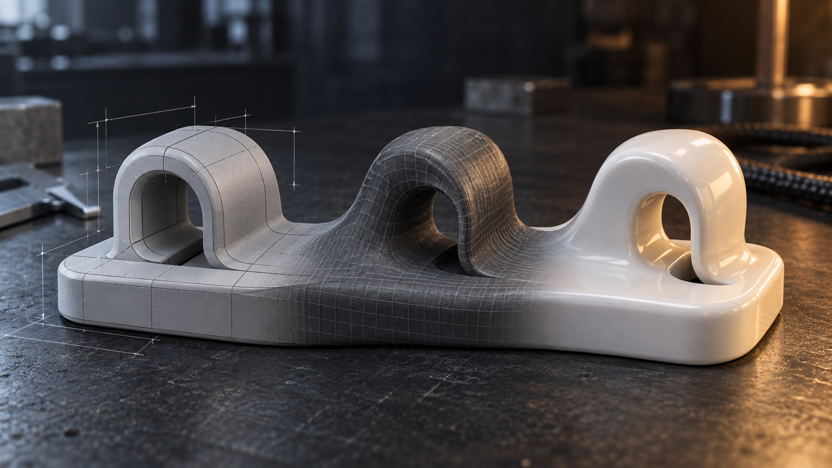
My First Print Exposed the Wrong Starting Point
My first successful print was a small box with my name engraved underneath. I modeled it in Blender and printed it on a Bambu Lab A1 Mini. Holding the finished part was satisfying. Getting there was less straightforward.
For a simple box, I had to work through Object Mode, Edit Mode, mesh faces, normals, Boolean operations, applied scale, manifold geometry, thin faces, STL export, and slicer inspection. One unit mistake sent the lettering far away from the box. Another produced an absurd size in the slicer. I even mistook a travel line in the preview for stray geometry.
Blender had done exactly what it was designed to do. The mismatch was mine: I needed to describe a functional object in dimensions, relationships, and clearances, but I had started in a mesh-oriented workflow.
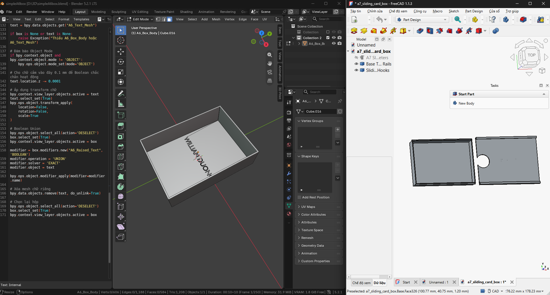
The same box problem invites two different workflows: Blender exposes Python and mesh operations, while FreeCAD organizes the object around Part Design, features, and real-world dimensions.
The source document is the original Google Docs research log.
The Printer Does Not Care How the Model Was Made
NIST describes additive manufacturing as creating an object directly from a 3D model by adding material, commonly layer by layer. The printer receives geometry; it does not care whether the geometry came from CAD, sculpting, or surface modeling.
A statue, a gear, and a mouse shell may all arrive in the slicer as STL or 3MF files. Upstream, however, their design work has little in common. A gear succeeds when dimensions and interfaces are correct. A figure succeeds when its form and pose feel convincing. A mouse shell depends on controlled curves and smooth transitions between surfaces.
By the time geometry reaches the slicer, the most important modeling decision has already been made.
CAD Starts with What Must Stay True
CAD starts from dimensions, geometric relationships, and function. A typical workflow is sketching a profile, adding dimensions and constraints, extruding material, cutting material, and assembling related parts.
For a groove under a box, the mental model is direct: select the bottom face, sketch a rectangle, enter its length and width, extrude to a defined depth, and choose Cut. The interface mirrors questions such as wall thickness, edge offsets, and clearance between two pieces.
This clicked for me because of the technical-drawing classes in the school curriculum I grew up with. We learned projections, line types, dimensions, and geometric relationships on paper. Parametric CAD extends that logic rather than replacing it: constrain the drawing, turn it into a solid, then compare the solid with the thing it must fit. An old classroom subject suddenly becomes a practical design method.
Boxes, lids, trays, brackets, clips, replacement parts, gears, and hinges all benefit from that method. FreeCAD, Fusion, Onshape, SolidWorks, and Inventor provide different implementations of it. I do not need to rank those brands before I can ask the more useful question: is this object mainly defined by measurable relationships?
Sculpting: When Form Comes First
Sculpting treats the model more like clay: build volume, push, pull, pinch, crease, and smooth. Blender describes Sculpt Mode as a free-form way to shape a mesh that is closer to traditional sculpting than editing individual vertices, edges, and faces.
This fits figures, faces, clothing, creatures, toys, rocks, trees, and other organic forms. The question is whether a cheek reads naturally or whether a pose has expression. A cheek protruding exactly 3.2 mm is rarely the first design constraint.
This is where Blender remains compelling. It also stays in my workflow for mesh repair, lettering, artistic details, materials, rendering, and animation. I am not replacing it; I am narrowing the jobs I ask it to do.
Surface Modeling: When the Curve Is the Product
Surface modeling uses geometry, but its main object of control is the curve and the quality of the surface rather than a collection of mechanical features. A simplified workflow draws guide curves, spans surfaces, adjusts curvature, joins surfaces smoothly, and adds thickness.
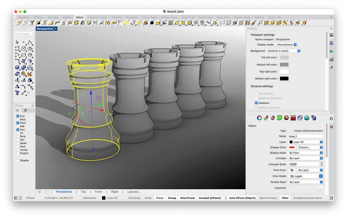
Mouse shells, handles, vehicle bodies, device enclosures, shoes, and lamps often live in this territory. Rhino, Plasticity, Alias, and the Surface or Form tools in Fusion expose curves and continuity as primary controls. Rhino, for example, uses NURBS to represent both exact circles and complex free-form surfaces. If a product will be judged by how one curve flows into the next, that concern belongs near the beginning of the workflow.
Three Workspaces, Three Kinds of Attention
| Direction | Main control | Success criterion |
|---|---|---|
| CAD | Dimensions and relationships | Measures correctly, fits, remains editable |
| Sculpting | Volume and surface gesture | Looks organic and expressive |
| Surface modeling | Curves and continuity | Holds a deliberate, smooth product shape |
Procedural tools cut across those categories. OpenSCAD, Grasshopper, and Blender Geometry Nodes generate geometry from rules and parameters; they change how construction is expressed, not necessarily what kind of object is being designed.
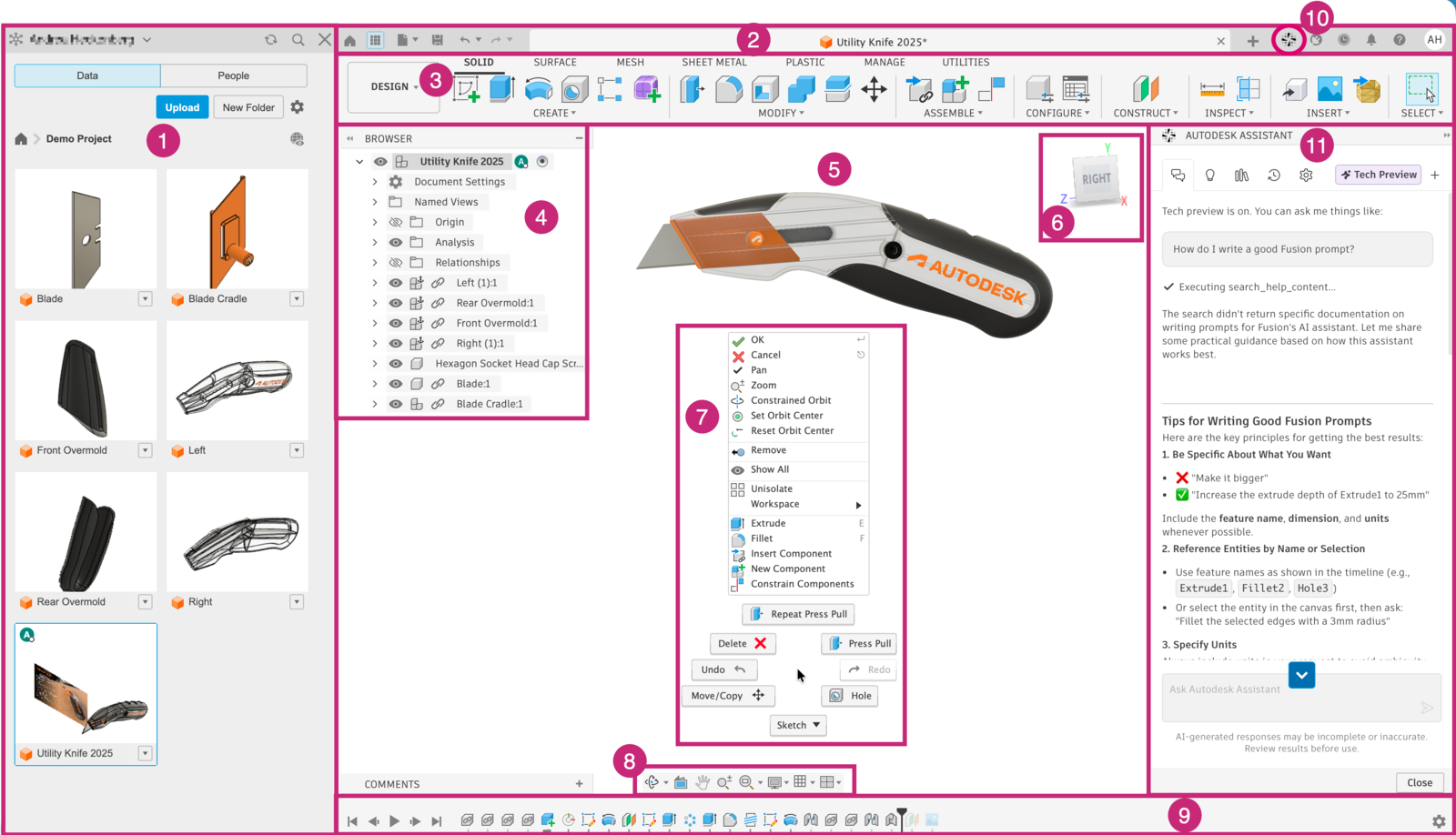
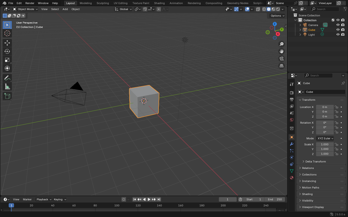
The screenshots below make the distinction tangible. FreeCAD and Fusion keep feature history, sketches, and mechanical operations close to the model. Blender centers a general-purpose 3D viewport and object hierarchy. Rhino surrounds the viewport with curve, surface, and inspection tools. None of these interfaces proves that one application is better. Each one reveals what the application expects the designer to pay attention to.


My Learning Path: FreeCAD First, Fusion Alongside It
The next objects on my list are ordinary, functional things: boxes, trays, brackets, hooks, clips, accessories, and replacement parts. Their dimensions come from calipers. Their sketches need constraints. Their features need to survive later edits. That puts CAD, rather than mesh modeling, at the center of my next learning phase.
I am starting with FreeCAD because the cost of trying it is zero. It is free and open source, works in real-world units, and records a parametric model history. That is enough for a beginner to move from a dimensioned sketch to an object that can be printed and tested without first making a software purchase.
FreeCAD also connects this experiment to my software background. Its Python console, macros, scripted objects, and custom workbenches make the model programmable. I want to find out where automation is genuinely useful: generating families of parts, changing dimensions from data, or producing drawings without repeating the same sequence by hand. That investigation deserves its own follow-up post, with working examples rather than promises.
Fusion will run alongside FreeCAD as a second reference point. It gives me another implementation of sketches, constraints, feature history, and manufacturing-oriented workflows. Comparing the same small object in both tools should teach me more than committing to a brand before I understand the method.
The print closes the loop: when a part does not fit, I can trace the failure back through orientation, clearance, dimensions, and the feature that produced them.
What I Will Ask Before Opening an Application
Before opening an application, I now ask what must remain under control. Dimensions and fit point me toward CAD. Organic volume points toward sculpting. Surface continuity points toward Rhino, Plasticity, or comparable surface tools. A mixed object may move through more than one application.
For my current work, the route is concrete: begin in FreeCAD, repeat selected exercises in Fusion, use Blender when mesh editing or decorative form earns its place, and finish in Bambu Studio for orientation, supports, and slicing. The software may change as the object changes.
That is the lesson I am carrying forward from the first box. Choosing a tool becomes much easier after I can name the kind of mistake I need the tool to prevent.
References
- NIST: Measurement Science for Additive Manufacturing
- NIST: Additive Manufacturing and 3D Printing
- Blender: Sculpting
- Blender: Modeling
- FreeCAD: Features
- FreeCAD: Power users hub and Python automation
- Autodesk Fusion: The Fusion interface
- Blender Manual: Window System Introduction
- Rhino: What are NURBS?
- Rhino: Features and interface
- OpenSCAD: About